
Fullwave Frequency Converter Welding Transformer
The fullwave frequency converter welding transformer utilizes the same principle as the halfwave frequency converter transformer. The FWFC is designed to output secondary currents in the range of 70,000 to 200,000 amperes by eliminating the effects of inductive impedance associated with large loop welding circuits.
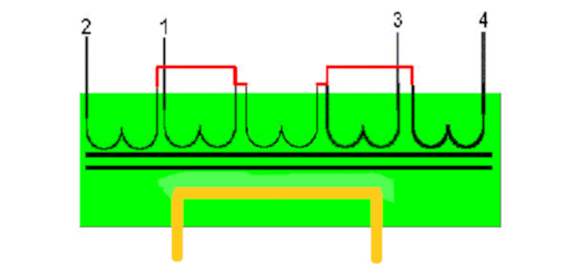
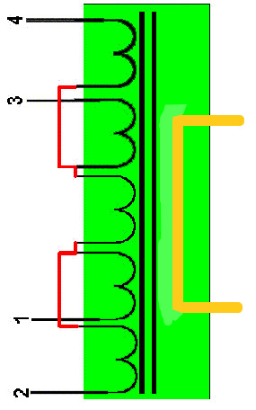
Each weld is performed by a single pulse of current in a given direction. That pulse may be more than one cycle period. There are five sets of primary windings surrounding a common magnetic core as shown above however there are always three windings in series to the voltage that is inputted by the welding control.
As you will see in a later page concerning the FWFC control, the current is made to flow from terminal 4 and out from terminal 1 on the positive pulsation. On negative pulsation, the current is made to flow from terminal 2 and out from terminal 3. Because there are three windings in series, the FWFC transformer is physically smaller than the HWFC transformer. Also, the ripple of the FWFC is much smaller than that of the HWFC.
Fullwave Frequency Converter Current Waveform
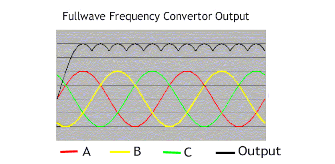
The welding current appears as shown. The reason why this waveform is called "fullwave" is due to the fact that both positive
and negative pulses contribute for each pulse of DC output. Shown here is only a positive output pulse. On the negative output pulses,
both positive and negative pulses of the 3-phase power supply will also contribute to the output. As shown, the output pulse is derived
from A+, C-, B+, A-, C+, B- and will continue for remaining cycles from A+ so on...Notice in the output curve shown in black line that there is no inter-cycle cooling periods where the current goes down towards zero. However since the complete full wave of each cycle contributes to the output, there is significant less ripple current at the top of the waveform. The ripple is equivalent to the three phase to DC system.