
Monitoring Using C-Factor
Must be used when welding in Current Regulation Mode
From this equation:

Simple Math:
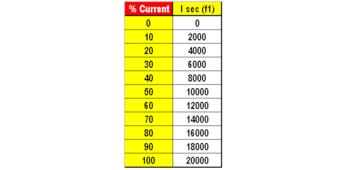
This simple expression would yield the truth table for a welder which can put out a maximum of 20,000 amperes. For example, if you want 10,000 amperes of output, you would need 50% of the maximum available current.
The following expression would follow:

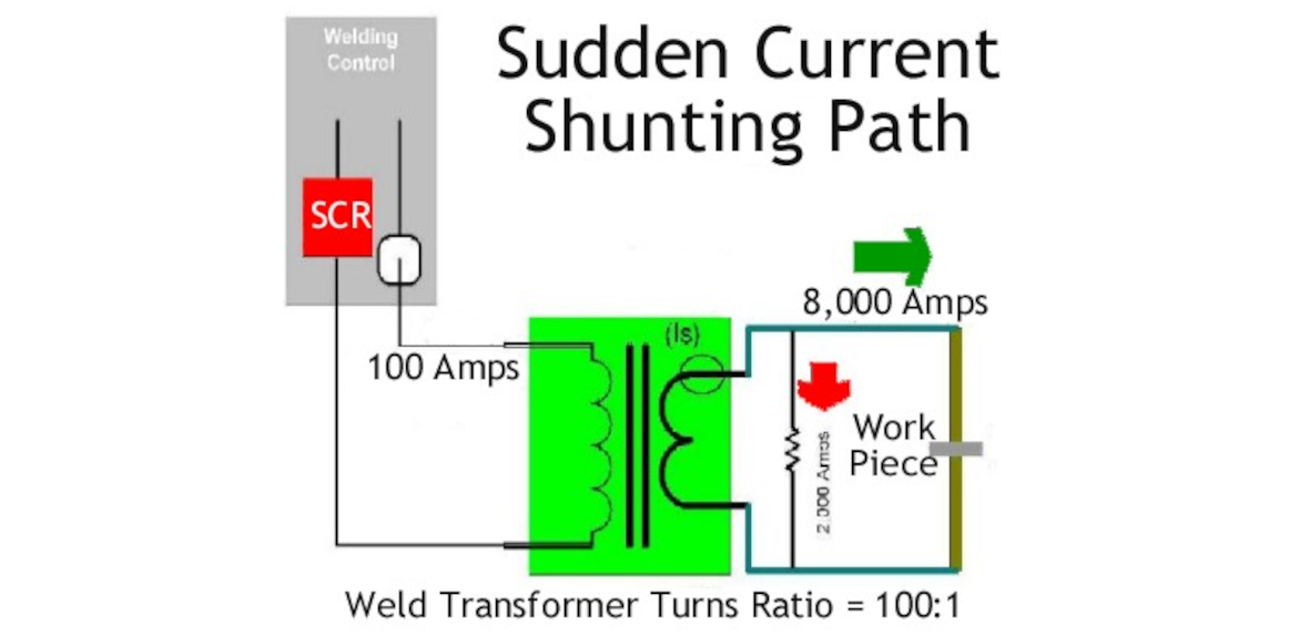
This equation is very useful for determining sudden current shunting conditions. The welding control does not know what is the welder's maximum available current however it can compute after each weld cycle pulse, the output current and the percentage that it fired. In this example, the control measures 10,000 amperes at 50% current, therefore the C-Factor will measure 200. This is the same as the maximum current (20,000 amperes) divided by 100.
C-Factor represents one percent of current increments.

Want more information?
 How to create an account